
Basic Science & Economics
Zero radiation surgery: A pilot study of MRI- based navigation in spine surgery
- Sahlgrenska University Hospital, Gothenburg, Sweden
- Institute of Clinical Sciences, Gothenburg, Sweden
- Drottning S, Gothenburg, Sweden
- Sahlgrenska University Hospital, Gothenburg, Sweden, Sweden
Abstract
Computer-assisted navigation to improve the accuracy of hardware placement during surgery usually rely on pre- or intraoperative computed tomography (CT). Radiation exposure from CT may contribute to iatrogenic malignancy. Technological advancements have enabled creation of synthetic CT-like images (sCT) from magnetic resonance imaging (MRI) data. The aim of this clinical study was to compare the use of sCT with standard CT for lumbar pedicle screw placement using surgical surface matched navigation and further to assess our first three patients with fully sCT navigated screws.
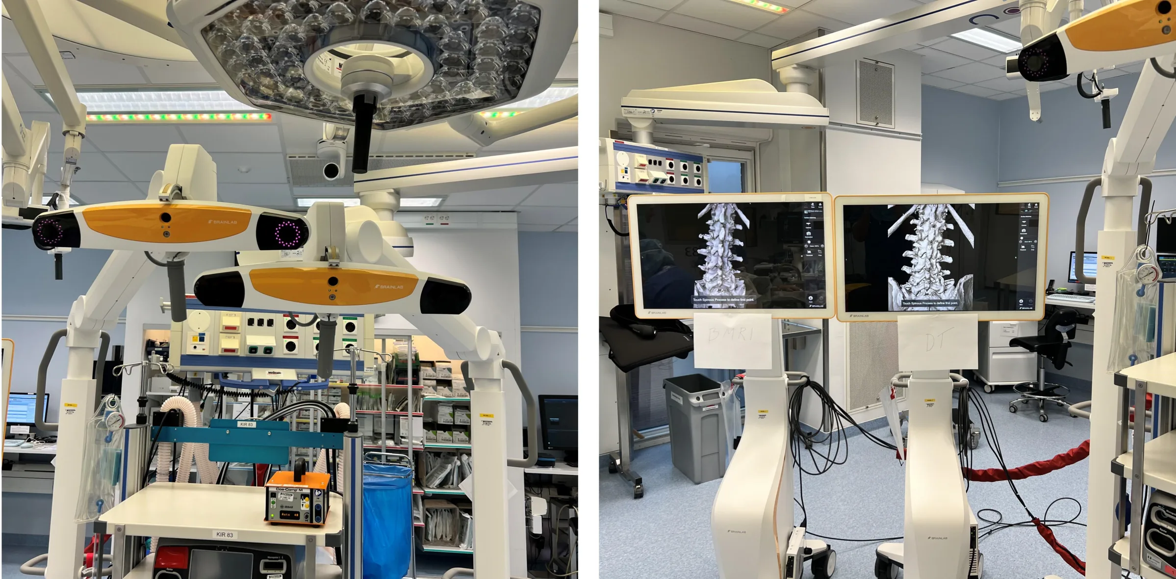
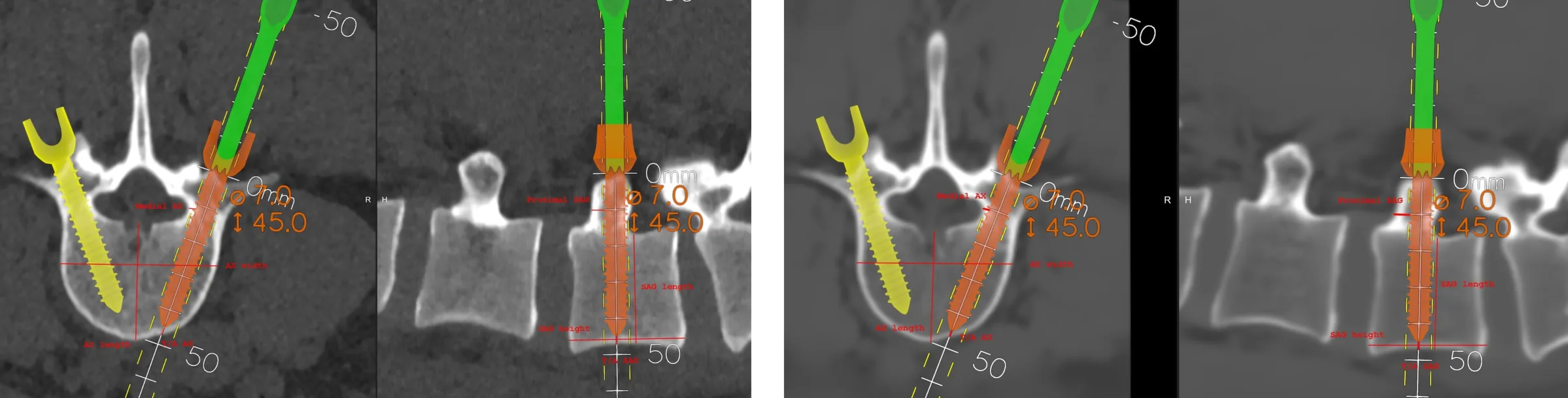
Preoperatively 5 lumbar fusion surgery patients were enrolled. Standard CT and custom MRI images (converted to sCT images using a commercial product) were obtained. Dual navigation, displaying the CT on one system and the sCT on the other, both calibrated via surface matching during the surgical procedure (Fig. 1). Navigation was performed using the CT, while synthetic CT served as a reference (“shadow”) system. Simultaneous screenshots captured navigated screw placements in the most proximal vertebra for each patient. Measurements of screw-to-bone cortex and bone-to-bone cortical distances were assessed: on axial views, screw tip-apex distance (ST/A AX), screw-to-medial-cortex distance (Medial AX) and vertebral with/length on sagittal views, screw tip-apex distance (ST/A SAG), screw-to-proximal-foraminal-edge distance (Proximal SAG) and vertebral height/length (Fig. 2). Mean ± SD were calculated and a paired comparison between CT and sCT was performed. After the CT/sCT comparison cohort, three patients were navigated using sCT (MRI) alone, and their screw placements were evaluated.
None of the screws using CT navigation crossed any cortical boundary when assessed on sCT views. The comparison between CT and sCT screw positions measurements showed mean (SD) differences of 0.2 (2.2) mm for ST/A AX, 0.4 (2.0) mm for ST/A SAG, 0.3 (1.0) mm for Medial AX, and 0.2 (0.9) mm for Proximal SAG. For vertebral measurements, the mean (SD) differences for AX width were 0.6 (2.9) mm, AX length 1.9 (1.0) mm, SAG height 0.8 (1.8) mm, and SAG length 1.8 (0.7) mm. In hardware-to-bone measurements and bone-to-bone (vertebral) measurements, 22/40 distances respectively 13/20 distances were longer on CT. All screws in the 3 sCT (MRI) navigated patients were confirmed placed correctly.
There were minimal and no systematic differences between the CT and sCT images in hardware-to-bone or vertebral measurements when using a surface-matched navigation system for lumbar pedicle screw placement. The sCT (MRI) images appeared to perform comparable to standard CT for surface-matched lumbar screw placement and the first three MRI/sCT navigated patients were performed without complications. This encourages further work with radiation-free navigation to limit radiation exposure for the patients.
Figures and tables
As submitted with the abstract. Tap a figure to open it at full size.